🎯 Key Points
- V_rms=V₀/√2; for R: V,I in phase; for L: I lags V by 90° (X_L=ωL); for C: I leads V by 90° (X_C=1/ωC)
- Impedance Z=√(R²+(X_L−X_C)²); resonance when X_L=X_C → ω₀=1/√(LC), Z=R (minimum), current is maximum
- Average power P=V_rms·I_rms·cosφ; power factor cosφ=R/Z (=1 for pure R, =0 for pure L or C — no real power dissipated)
- Transformer: V₂/V₁=N₂/N₁=I₁/I₂ — step-up increases voltage but decreases current proportionally (power conserved ideally)
- Quality factor Q=ω₀L/R — higher Q means sharper, more selective resonance (used in radio tuning)
In a pure inductor the current lags the voltage by 90° (energy is briefly stored in the magnetic field before current responds); in a pure capacitor the current leads the voltage by 90° (current must flow to build up charge before voltage rises) — the mnemonic "ELI the ICE man" keeps these straight.
AC Basics
- v = V₀·sin(ωt); i = I₀·sin(ωt + φ)
- RMS values: V_rms = V₀/√2; I_rms = I₀/√2
- Angular frequency: ω = 2πf
Pure Elements in AC
- Resistor R: V and I in phase; V_R = IR
- Inductor L: I lags V by 90°; X_L = ωL = 2πfL (inductive reactance)
- Capacitor C: I leads V by 90°; X_C = 1/ωC = 1/2πfC (capacitive reactance)
Series LCR Circuit
- Impedance: Z = √(R² + (X_L - X_C)²)
- Phase angle: tan(φ) = (X_L - X_C)/R
- Current: I = V/Z
- Resonance: X_L = X_C → ω₀ = 1/√(LC); Z = R (minimum), I is maximum
- Quality factor: Q = ω₀L/R = 1/ω₀CR = (1/R)√(L/C)
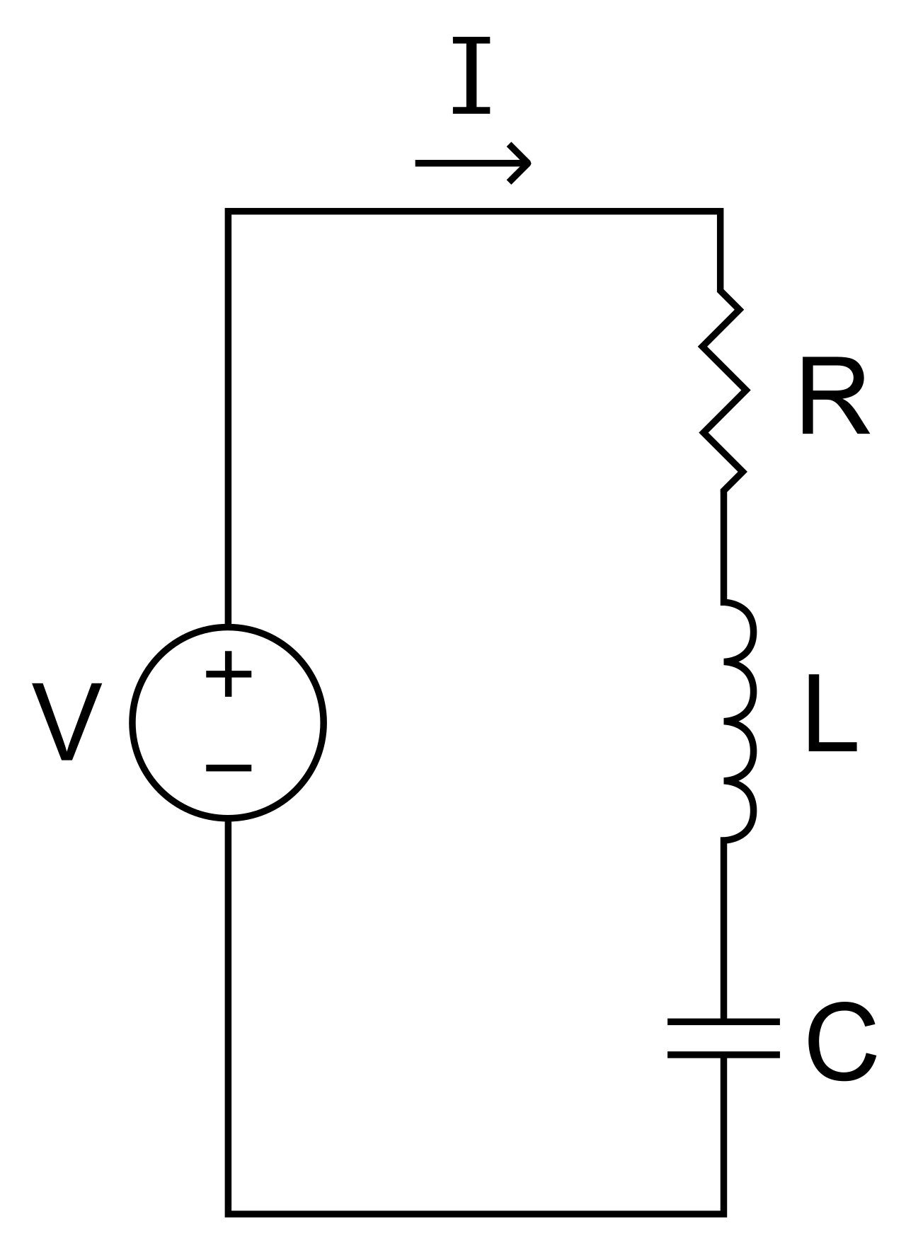
Series LCR circuit: Z = √(R² + (X₃ − X₊)²), and at resonance X₃ = X₊ so Z = R and the current is maximum. Image: V4711, CC BY-SA 3.0, via Wikimedia Commons.
Power in AC
- Instantaneous power: p = vi
- Average power: P_avg = V_rms·I_rms·cos(φ)
- Power factor: cos(φ) = R/Z (= 1 for resistor, 0 for pure L or C)
- Wattless current: component of I that contributes no power
Transformers
- V₂/V₁ = N₂/N₁ = I₁/I₂ (ideal transformer)
- Step-up: N₂ > N₁ (voltage increases, current decreases)
- Step-down: N₂ < N₁ (voltage decreases, current increases)
- Energy losses: copper loss (I²R), iron loss (eddy currents, hysteresis)
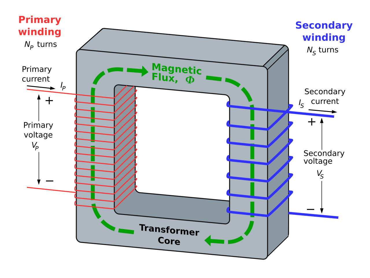
Transformer: flux linked through a common core gives Vₛ/Vₚ = Nₛ/Nₚ, and for an ideal transformer VₚIₚ = VₛIₛ. Image: BillC, CC BY-SA 3.0, via Wikimedia Commons.
RMS and Average Values
- RMS (root mean square) value is the value of steady current that produces the same heating effect as the AC over a full cycle; for sinusoidal AC, I_rms = I₀/√2 ≈ 0.707 I₀
- Average value of AC over a full cycle is zero; average over half cycle: I_avg = 2I₀/π ≈ 0.637 I₀
- Form factor = RMS value / average value (over half cycle) = π/(2√2) ≈ 1.11 for sinusoidal AC
LC Oscillations
- A charged capacitor connected to an inductor (no resistance) produces electrical oscillations analogous to SHM
- Angular frequency of free oscillation: ω = 1/√(LC), same as the series resonance condition
- Energy oscillates between the electric field of the capacitor and the magnetic field of the inductor, with total energy conserved (in the ideal, resistance-free case)
Half Power Frequencies and Sharpness of Resonance
- At resonance, current is maximum (I₀ = V/R) and the LCR circuit behaves purely resistively
- Sharpness of resonance is measured by quality factor Q; higher Q means a narrower resonance curve and better frequency selectivity (important in radio tuning circuits)
- Bandwidth of resonance: Δω = ω₀/Q (the smaller the bandwidth, the sharper the resonance)
Frequency Dependence of Reactance
- Inductive reactance X_L = ωL = 2πfL increases linearly with frequency — an inductor blocks high frequencies but passes DC freely (at f = 0, X_L = 0, so it behaves like a plain wire)
- Capacitive reactance X_C = 1/ωC = 1/(2πfC) decreases with frequency — a capacitor passes high frequencies but blocks DC (at f = 0, X_C is infinite, so no steady current flows through it)
- This opposite behaviour is why an inductor is used as a choke to filter high-frequency noise, while a capacitor is used to block DC and couple AC signals between stages
Phasor Representation of AC Quantities
- A phasor is a rotating vector whose length represents the peak value of an AC quantity and whose angle represents its instantaneous phase; its projection on the vertical axis gives the instantaneous value
- Because V and I are generally out of phase, they are drawn as phasors separated by the phase angle φ, and the voltages across R, L, and C are combined as vectors rather than as plain numbers
- In a series LCR circuit the V_R phasor lies along the current, V_L leads it by 90°, and V_C lags it by 90°; combining them geometrically gives the resultant voltage and the impedance triangle (R, X_L − X_C, Z)
Power Factor and AC Power Transmission
- The power factor cosφ = R/Z is the fraction of the apparent power (V_rms·I_rms) that is converted into useful work; the remainder merely oscillates back and forth between source and reactive elements
- A low power factor forces a larger current to deliver the same real power, raising I²R losses in the lines — so industries improve it by adding capacitors to cancel inductive lag
- AC is preferred for long-distance transmission because transformers can step the voltage up (reducing current and hence I²R line loss) and step it back down for safe domestic use
🚀 JEE Advanced Edge
Choke coil: A pure inductor (ideally zero resistance) used to limit AC current without dissipating power, since cosφ=0 for a pure inductor — used in fluorescent tube ballasts instead of a resistor, which would waste power as heat.
Phasor diagram method: Representing V_R, V_L, V_C as vectors (phasors) at 0°, 90°, and −90° respectively lets you add them vectorially to find total voltage/impedance — V_L and V_C phasors are anti-parallel and partially cancel, which is why impedance uses (X_L−X_C), not (X_L+X_C).
Worked problem: A series LCR circuit has R=30Ω, X_L=50Ω, X_C=10Ω, connected to a 200V (rms) AC source. Find the impedance, current, and power factor. Approach: Z=√(R²+(X_L−X_C)²)=√(900+1600)=√2500=50Ω. I=V/Z=200/50=4A. cosφ=R/Z=30/50=0.6 (lagging, since X_L>X_C).